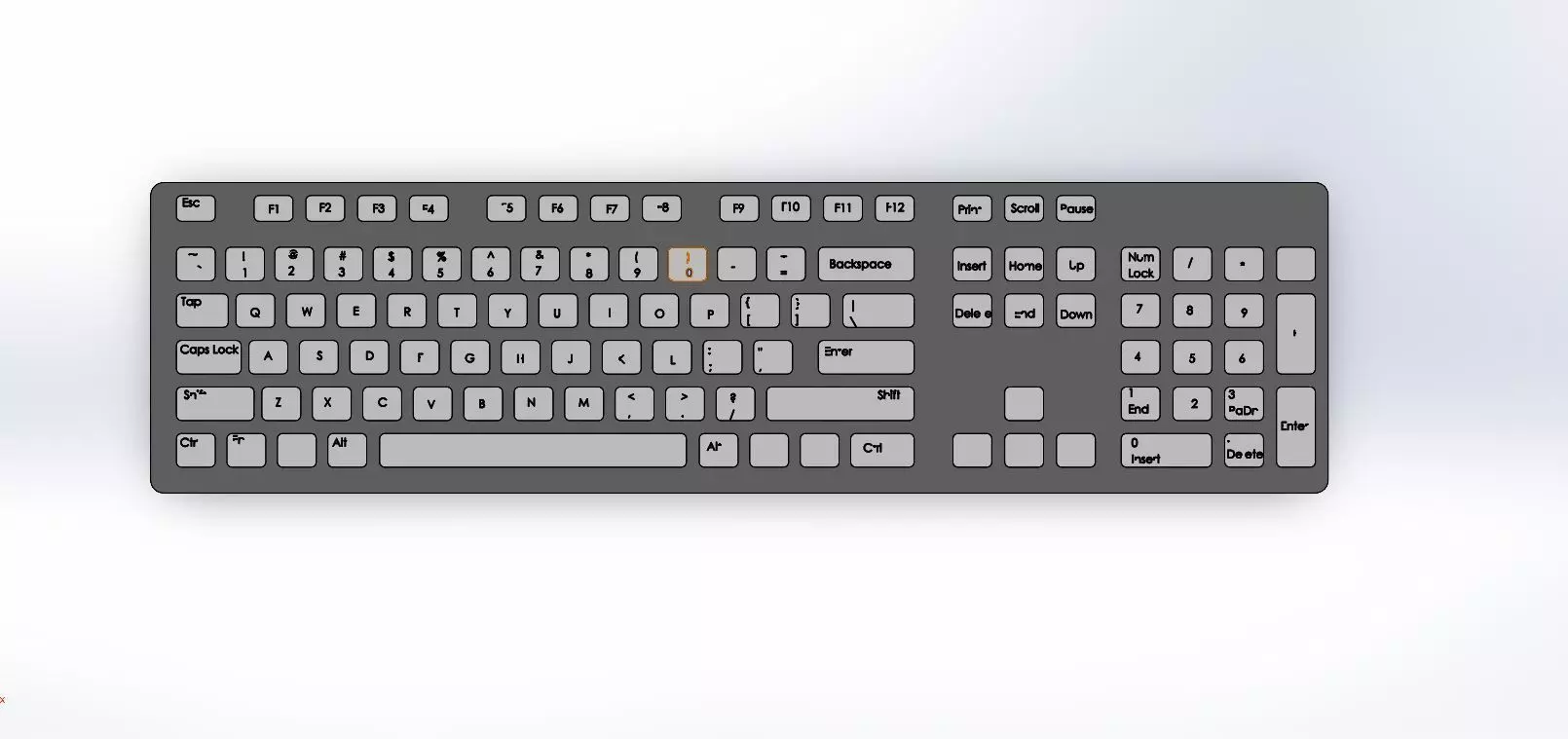
Creating a computer keyboard model in SolidWorks involves several steps, from initial sketching to final assembly. Here’s a step-by-step guide to help you design a basic computer keyboard:
- Setup Your ProjectOpen SolidWorks: Start SolidWorks and create a new part or assembly document depending on how you want to approach the design.
- Design the KeycapsCreate a Keycap Profile:
New Part: Open a new part file.Sketch: Select a plane (e.g., Top Plane) and create a sketch for the keycap profile. Use tools like Rectangle or Circle to draw the basic shape.Extrude: Use the Extruded Boss/Base feature to give thickness to the keycap.Create Keycap Details:
Add features like a recess for the switch and any other details using Extruded Cuts or Revolved Cuts.Create Multiple Keycaps:
Use the Mirror or Pattern feature to duplicate the keycap design if the keycaps are the same.
- Design the Keyboard BaseCreate the Keyboard Base Profile:
New Part: Open a new part file for the base.Sketch: Select the Top Plane and sketch the outline of the keyboard base. Draw the rectangle or custom shape that will house the keycaps.Extrude: Use the Extruded Boss/Base feature to create the thickness of the keyboard base.Add Mounting Features:
Sketch and extrude features to hold the keycaps. You might want to create holes or slots for keycap mounts.
- Design the Keyboard FrameCreate the Frame Profile:
New Part: Open a new part file for the frame.Sketch: Create a sketch of the frame that surrounds the keyboard base. This could include additional structural elements.Extrude: Use Extruded Boss/Base to give the frame thickness.Add Assembly Features:
Sketch and extrude mounting points or screw holes if needed for attaching the frame to the base.
- Assemble the KeyboardCreate an Assembly Document:
Open a new assembly document in SolidWorks.Insert Components:
Use the Insert Components feature to add your base, frame, and keycaps into the assembly.Arrange the components using the Mate feature to position and align them properly.Adjust Keycap Placement:
Use Assembly features like Mate to ensure each keycap fits into the correct position on the base.
- Add Additional DetailsDesign Switches:
Create models for mechanical switches or membrane switches if you want to include them in your design.Add these components to your assembly.Detailing:
Add any additional details like legends on the keycaps, texture, or labels.
- Final TouchesCheck Dimensions: Ensure all components are correctly sized and positioned.Render: Use SolidWorks’ rendering tools to create realistic images of your keyboard design.Create Technical Drawings: Generate detailed technical drawings if needed for manufacturing or presentation.Additional TipsReference Images: Import images or sketches into SolidWorks to use as reference for your design.Keyboard Layout: You might want to research and include a specific keyboard layout or configuration depending on your requirements.Keyboard Parts: If designing a full-scale model, consider components such as the PCB (Printed Circuit Board), connectors, and backlighting.SolidWorks provides powerful tools to model complex geometries, so make use of its various features like sketches, extrusions, patterns, and assemblies to create a detailed and functional keyboard design.