

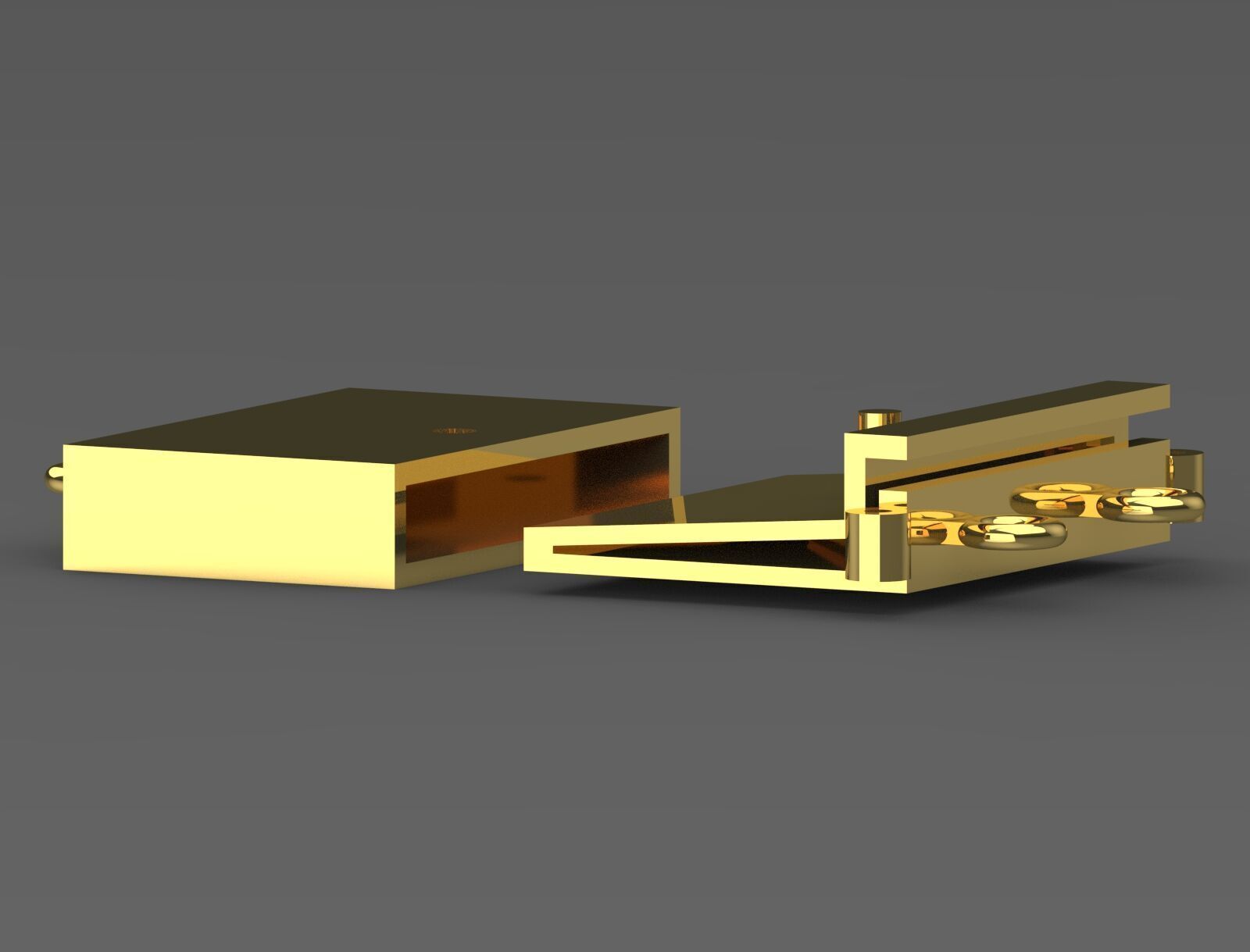
necklace gold claps gl0003 3D print model
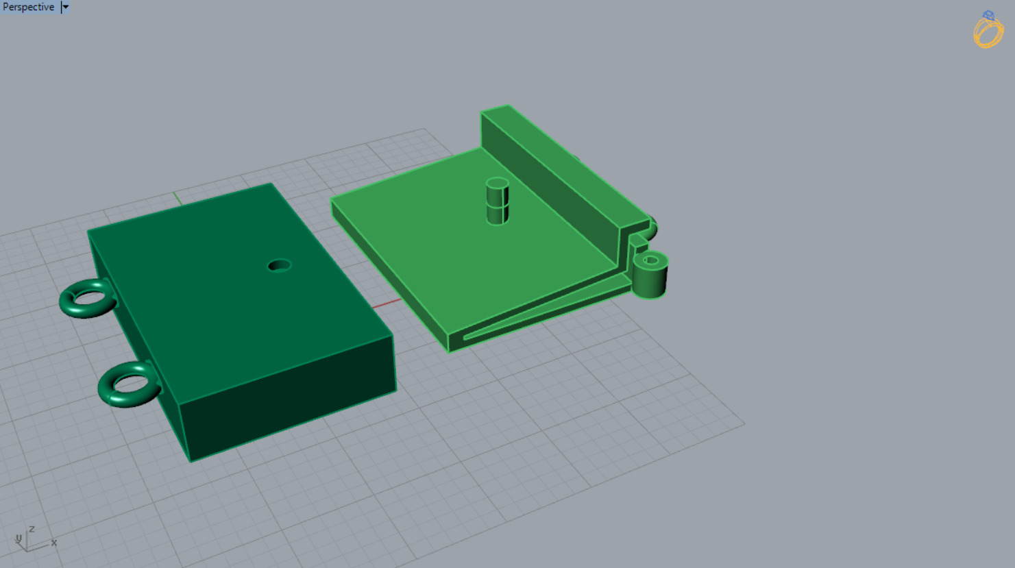
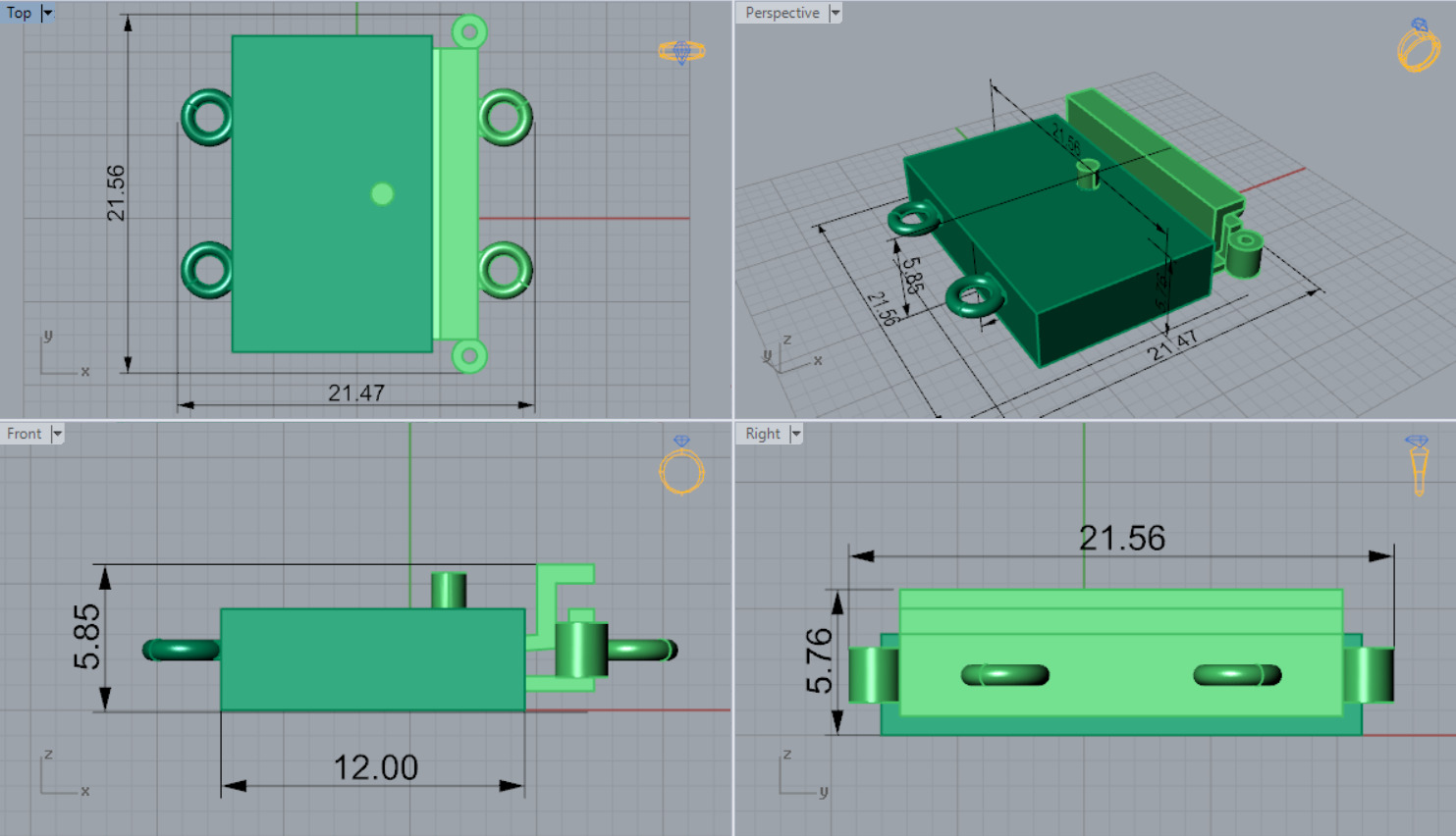
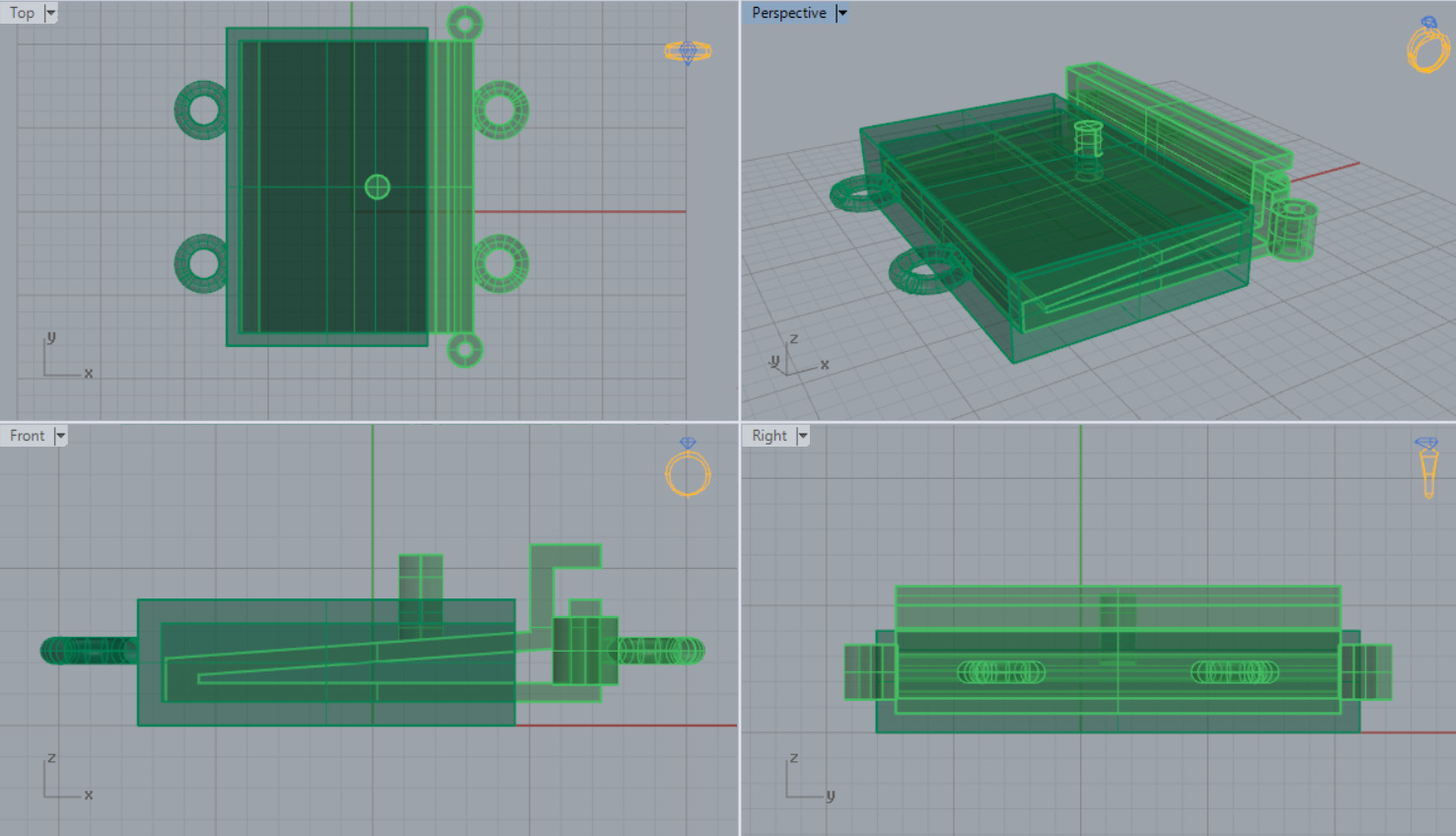
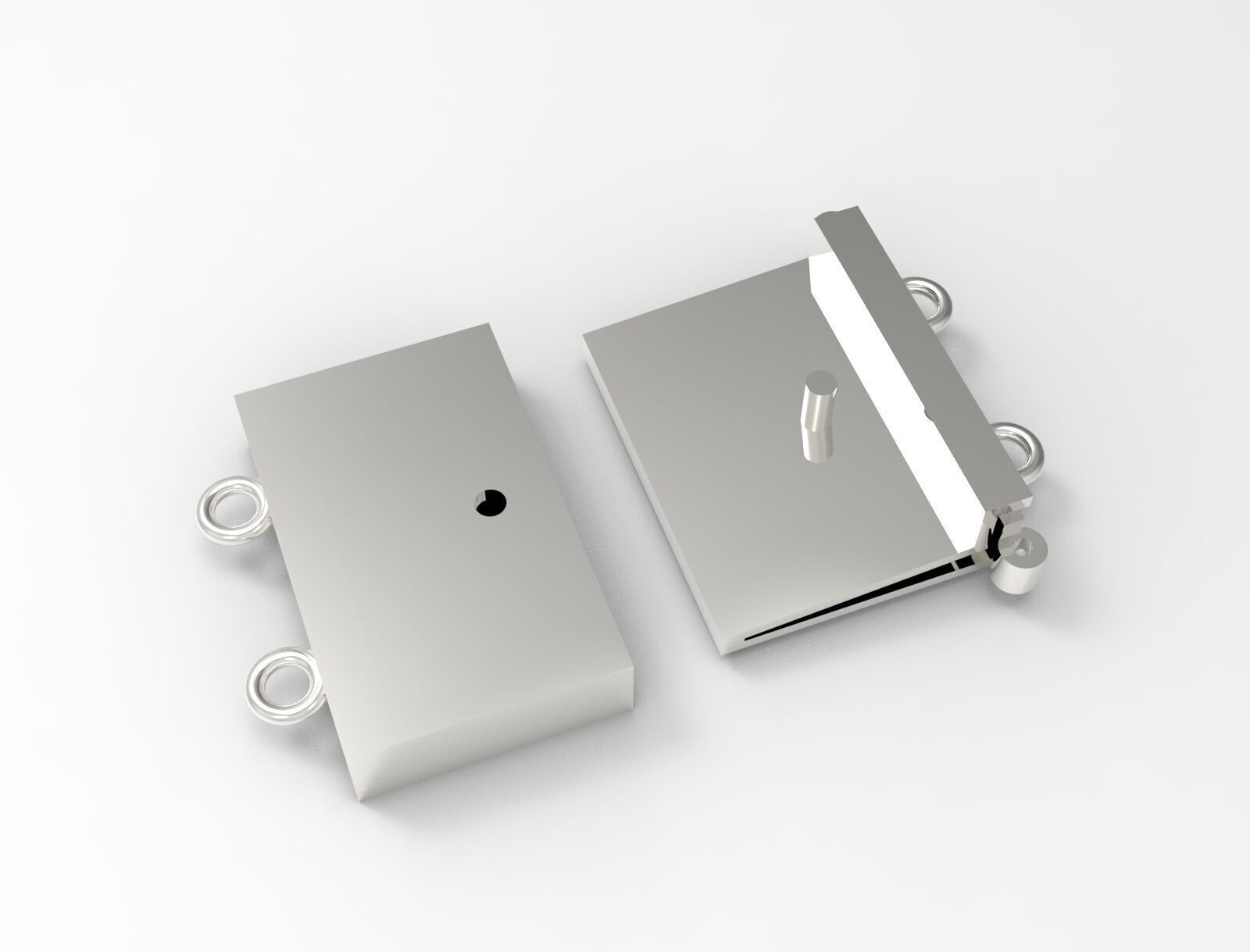
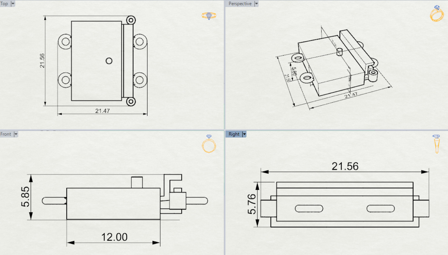
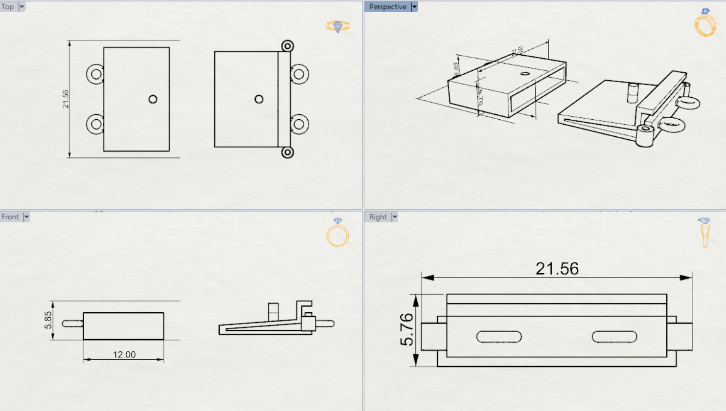
The image presents a technical drawing and 3D model of a rectangular mechanical component, showcasing its design from various views:
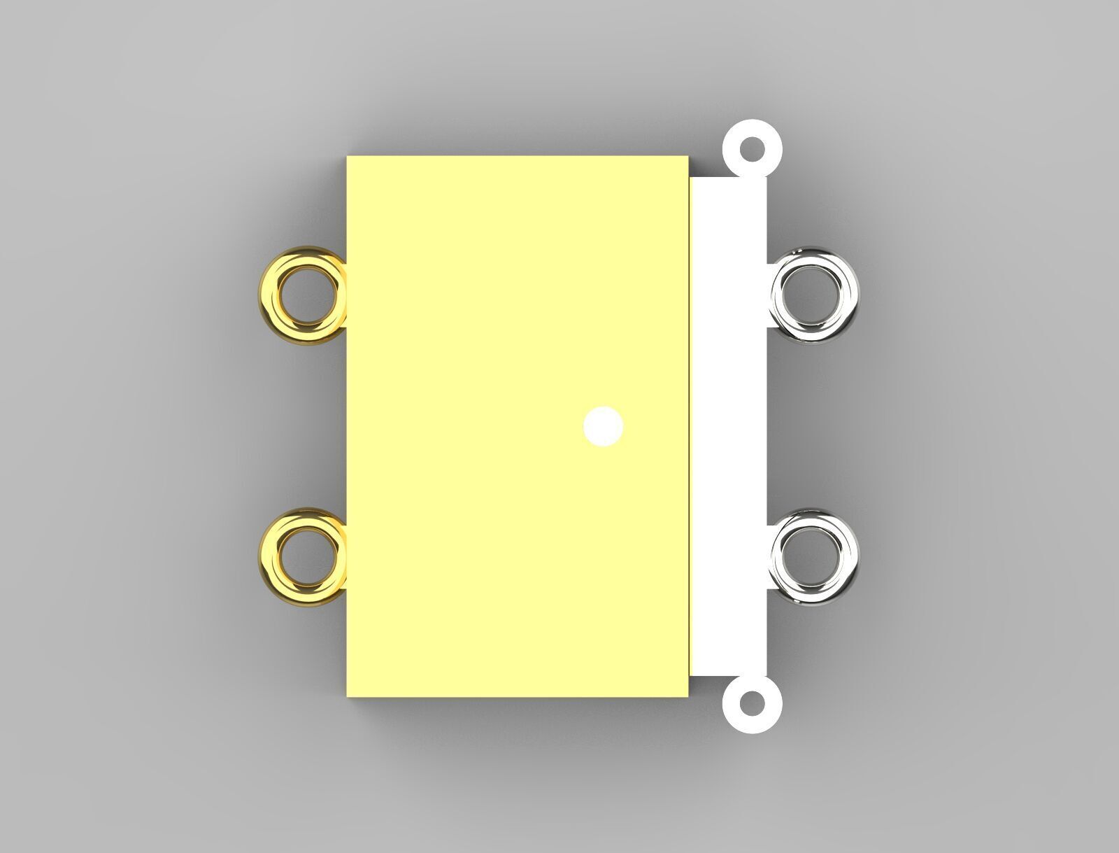
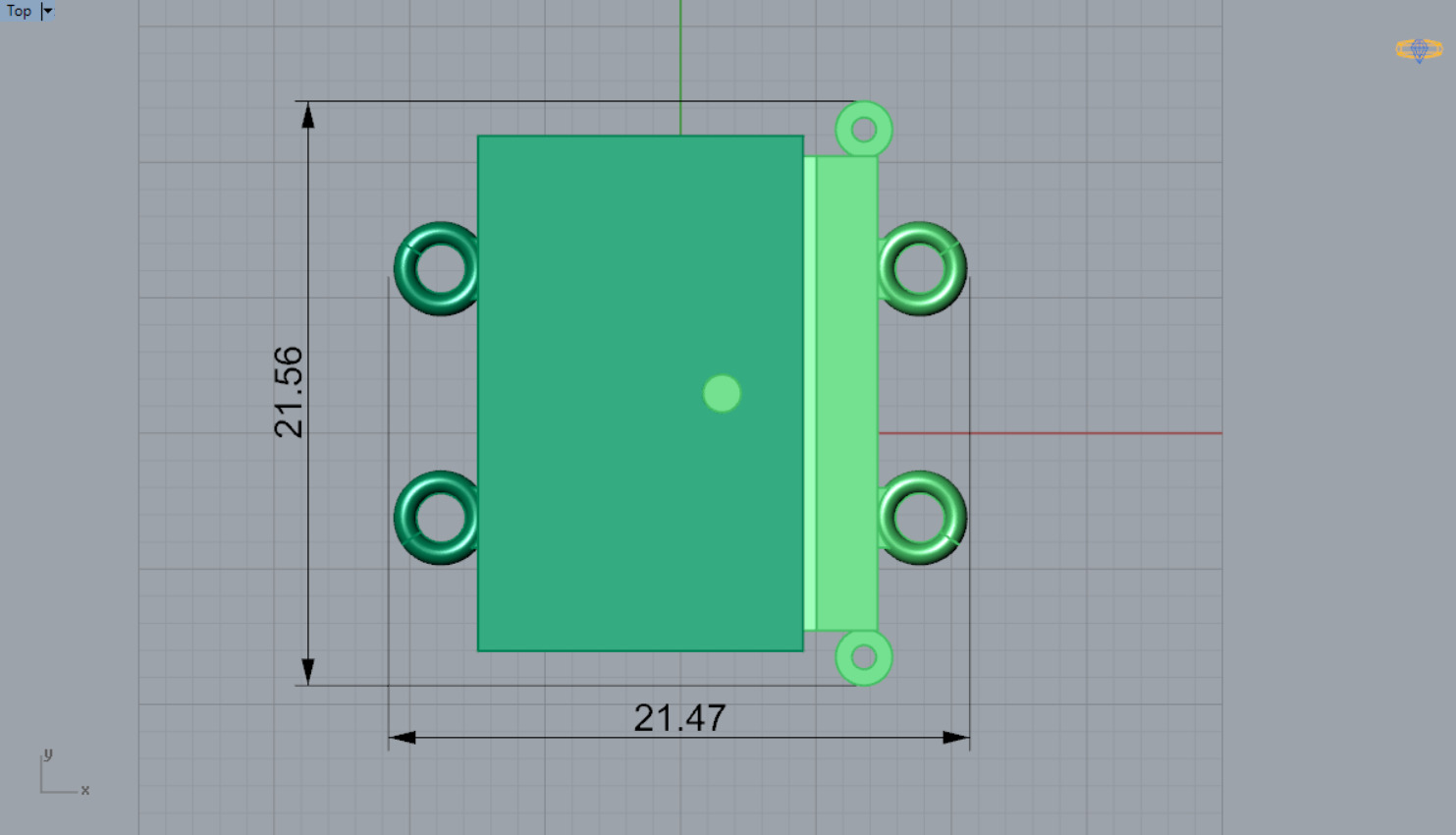
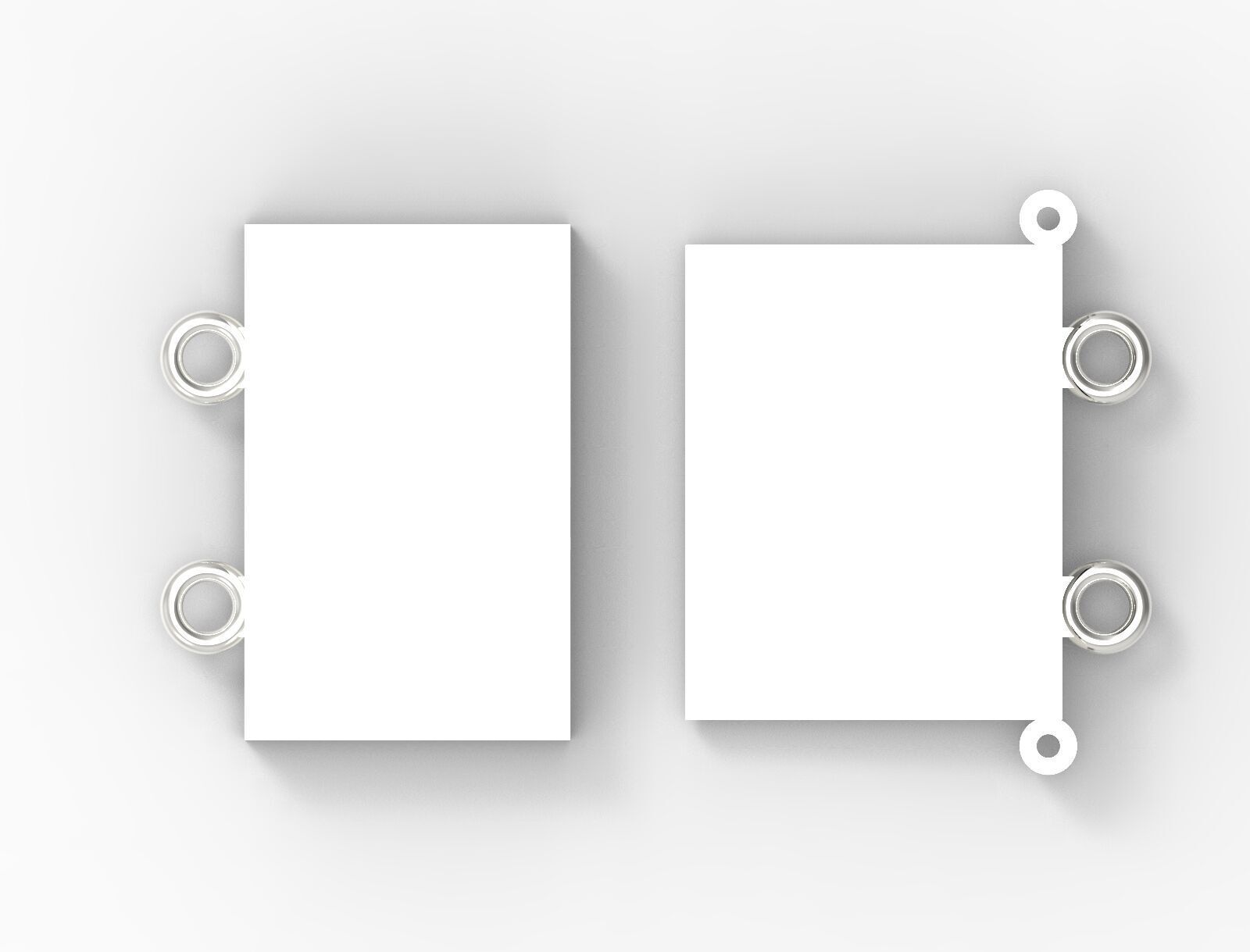
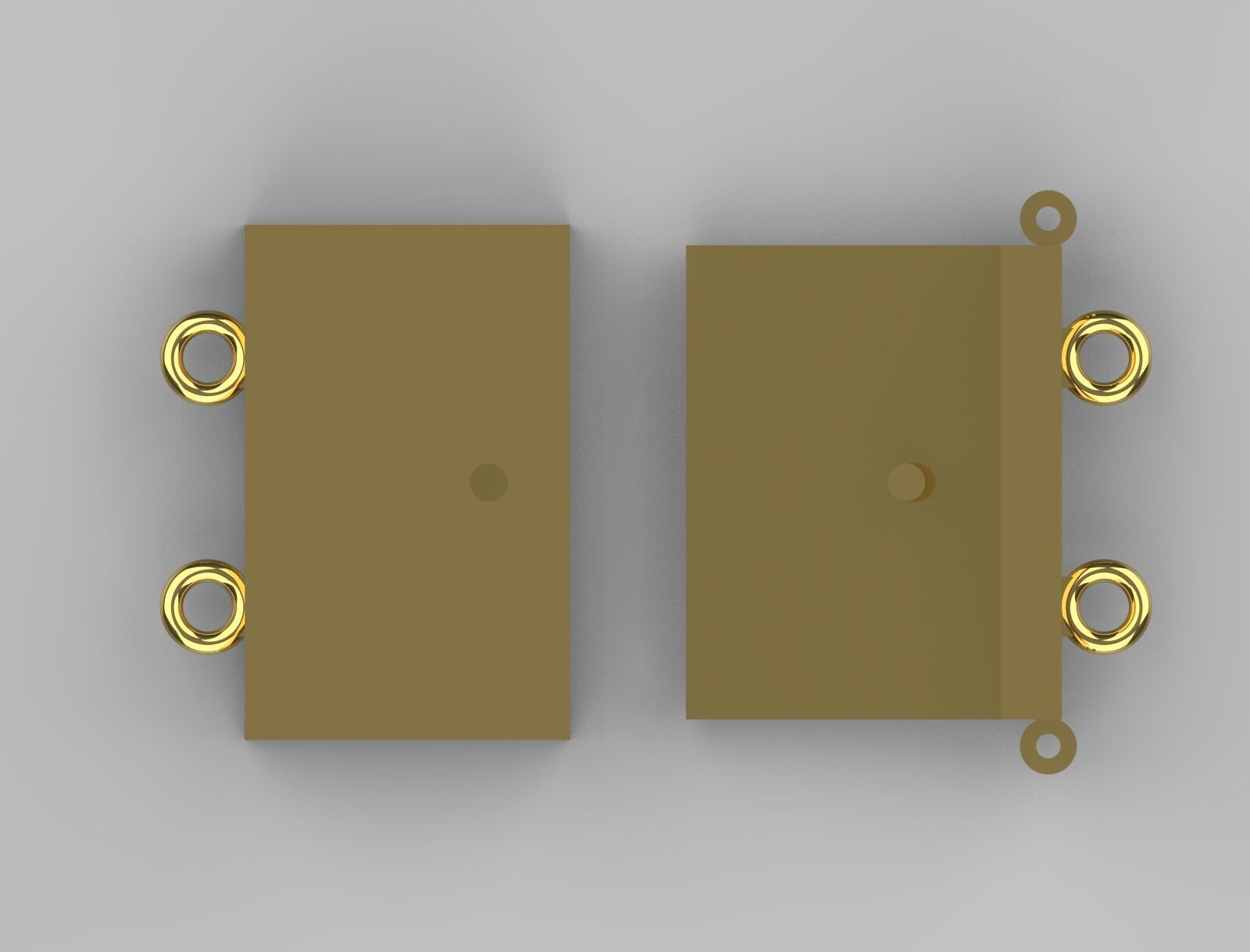
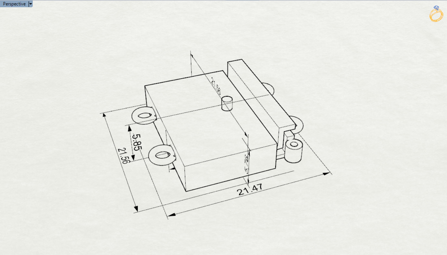
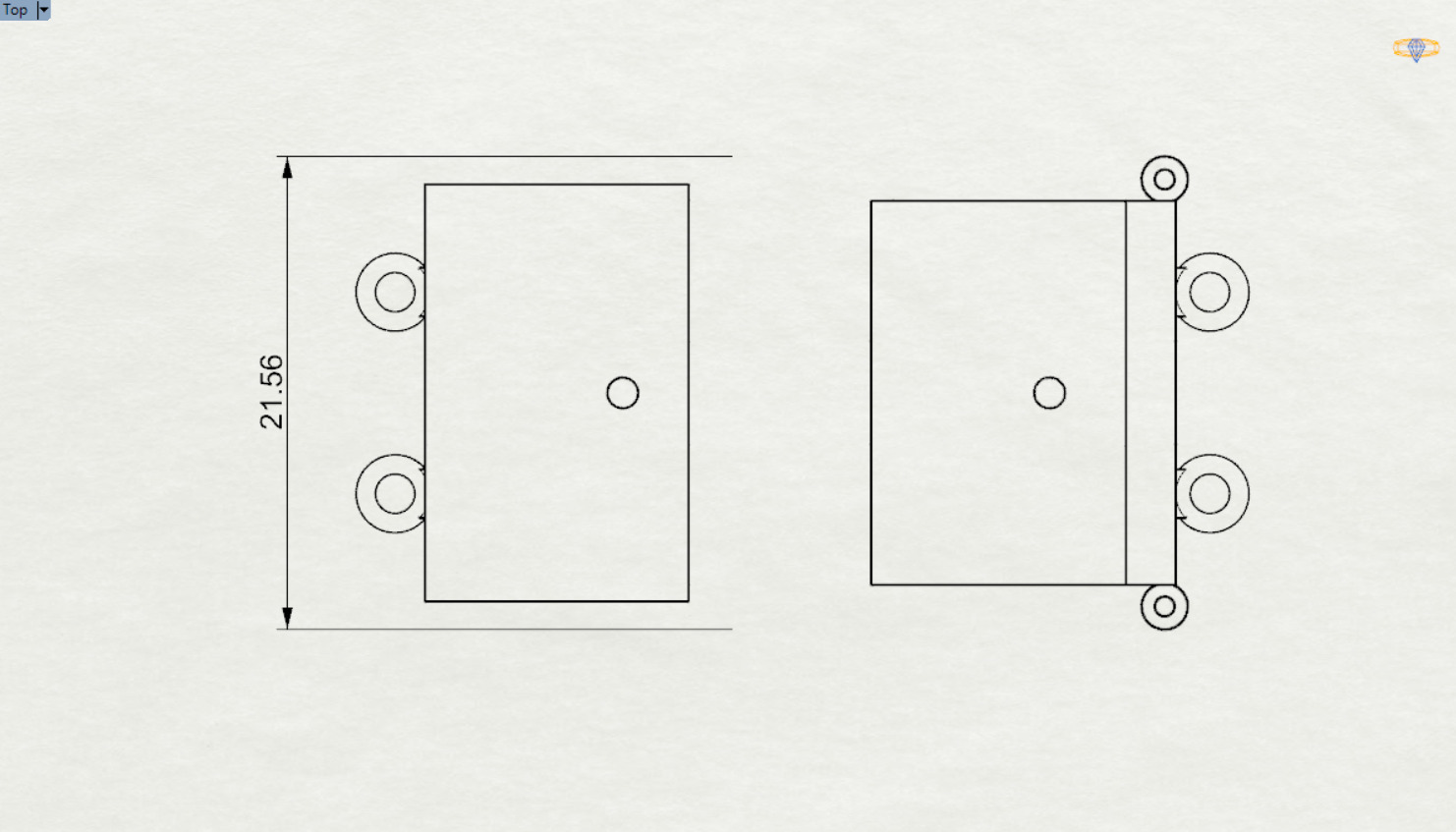
Top View: Displays the outline of the component, including key dimensions (21.56 in width). It also shows features like two circular cutouts and a central hole, likely for attachment or alignment purposes.
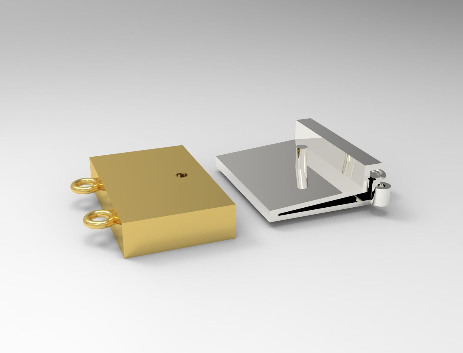
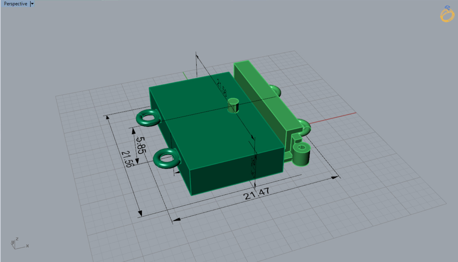
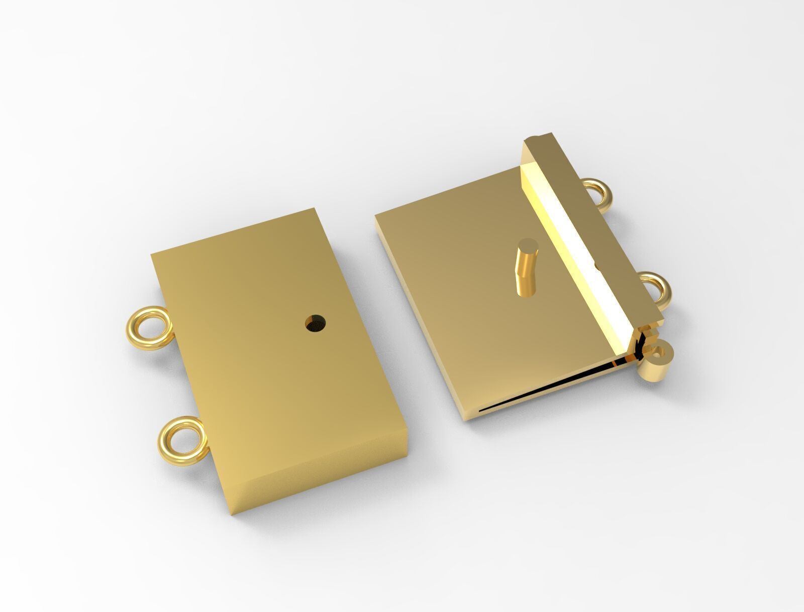
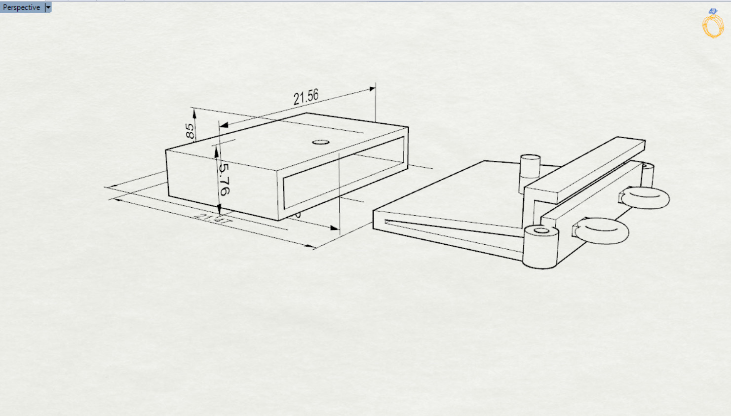
Perspective View: Offers a 3D representation, allowing for a better understanding of the component's depth and overall shape. It highlights the layout of features, such as the cutouts and any potential mechanisms.
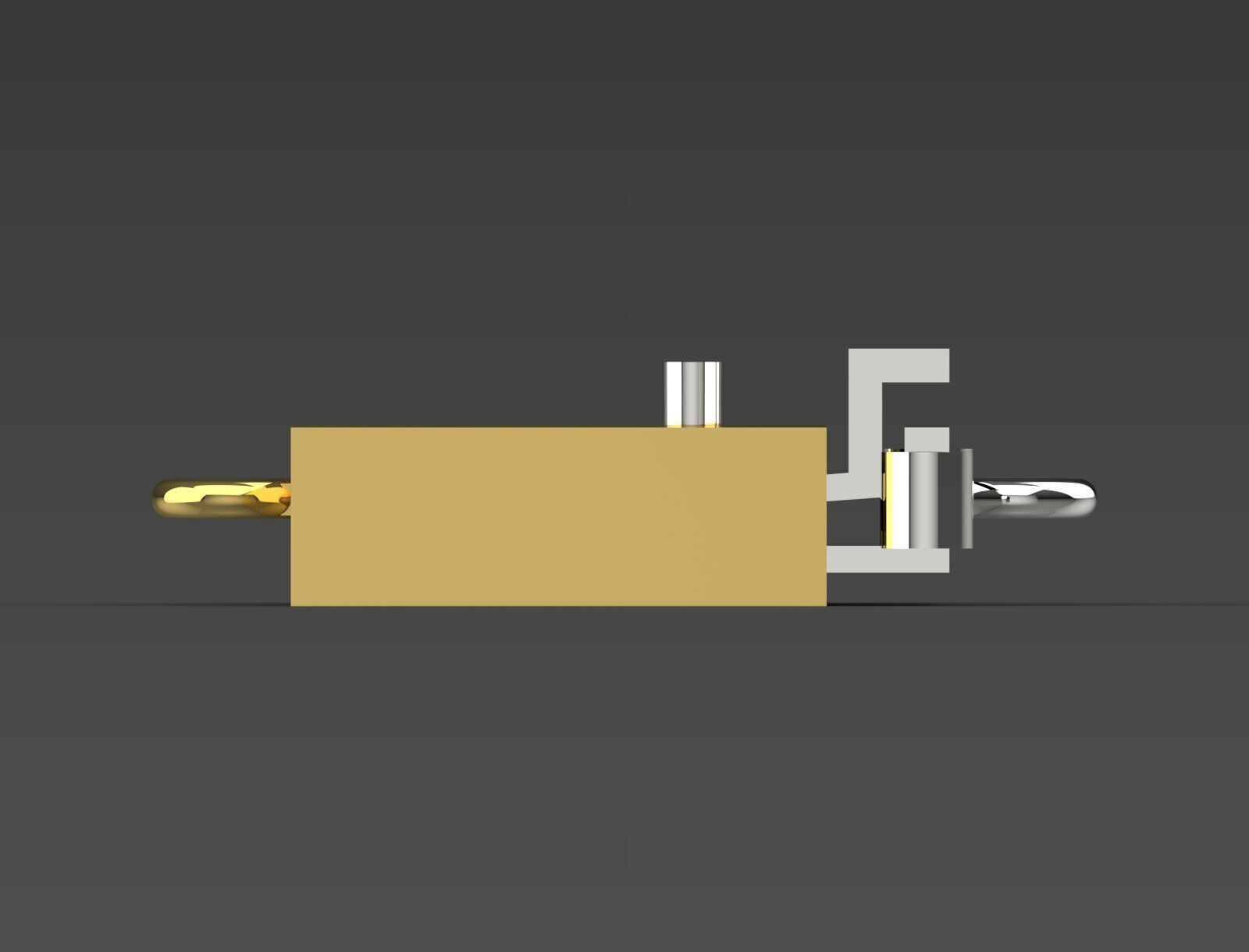
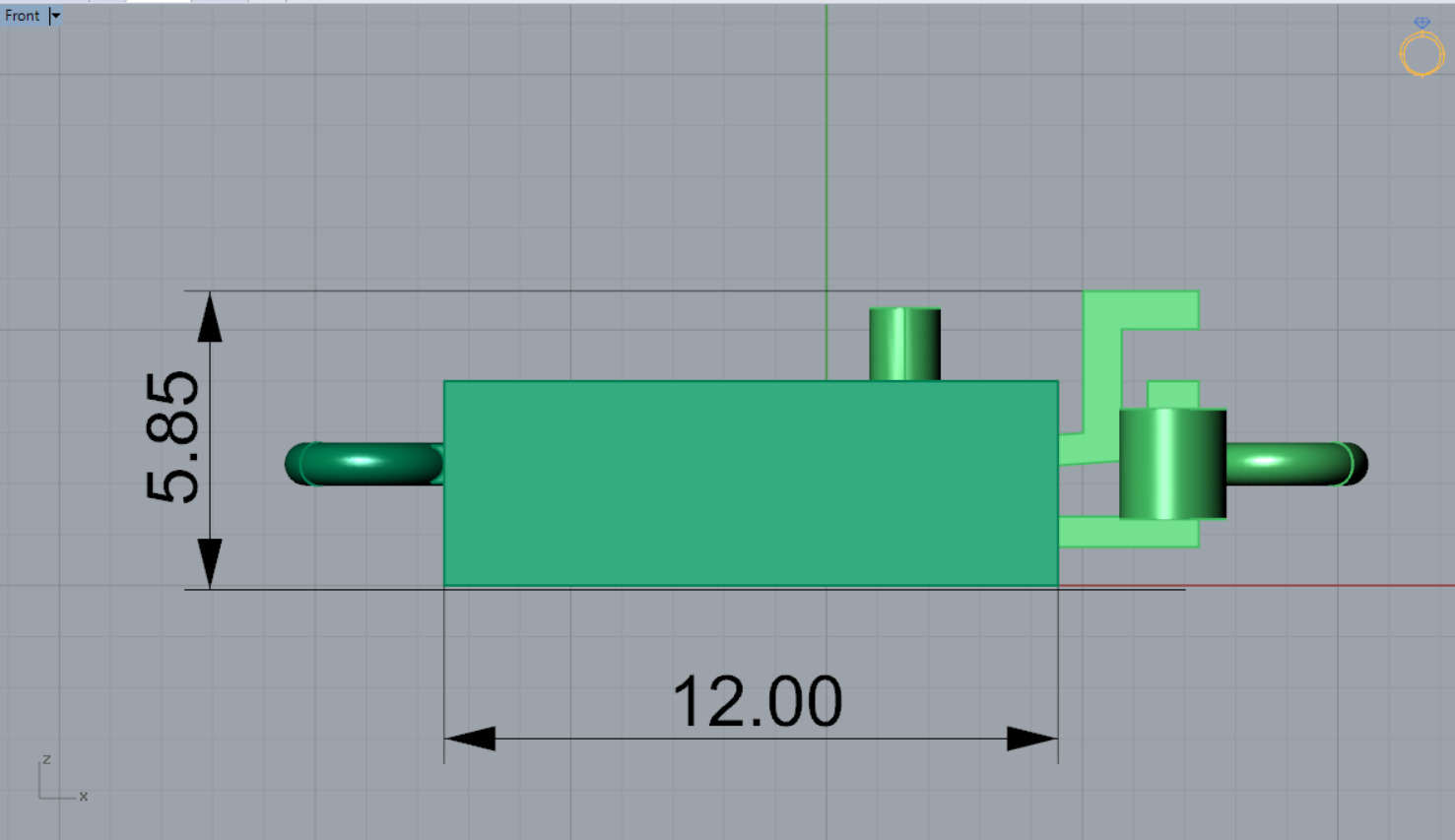
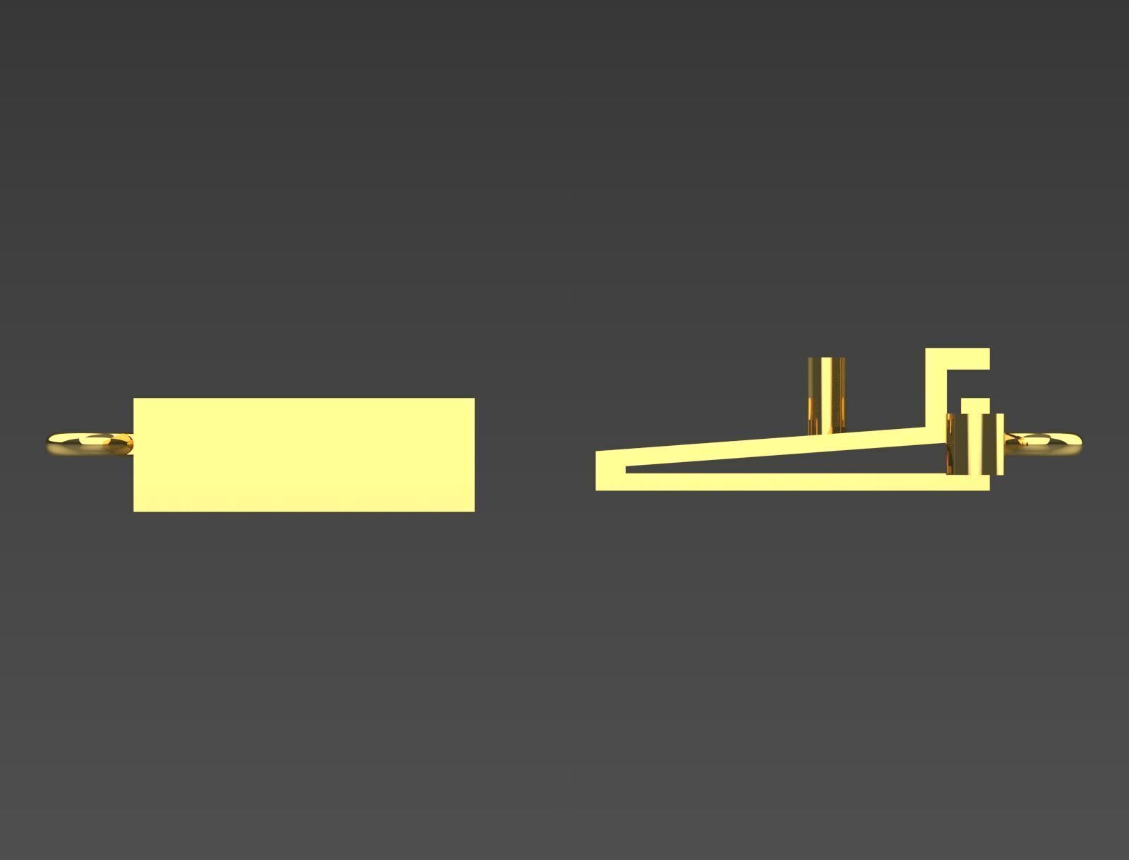
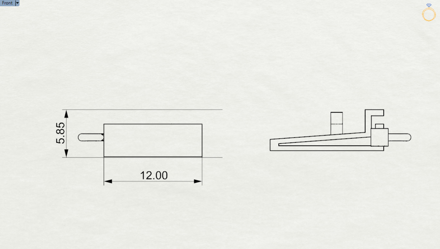
Front View: This view provides the height (5.85) and indicates the position of features like the cylindrical protrusion (likely for connection or mounting).
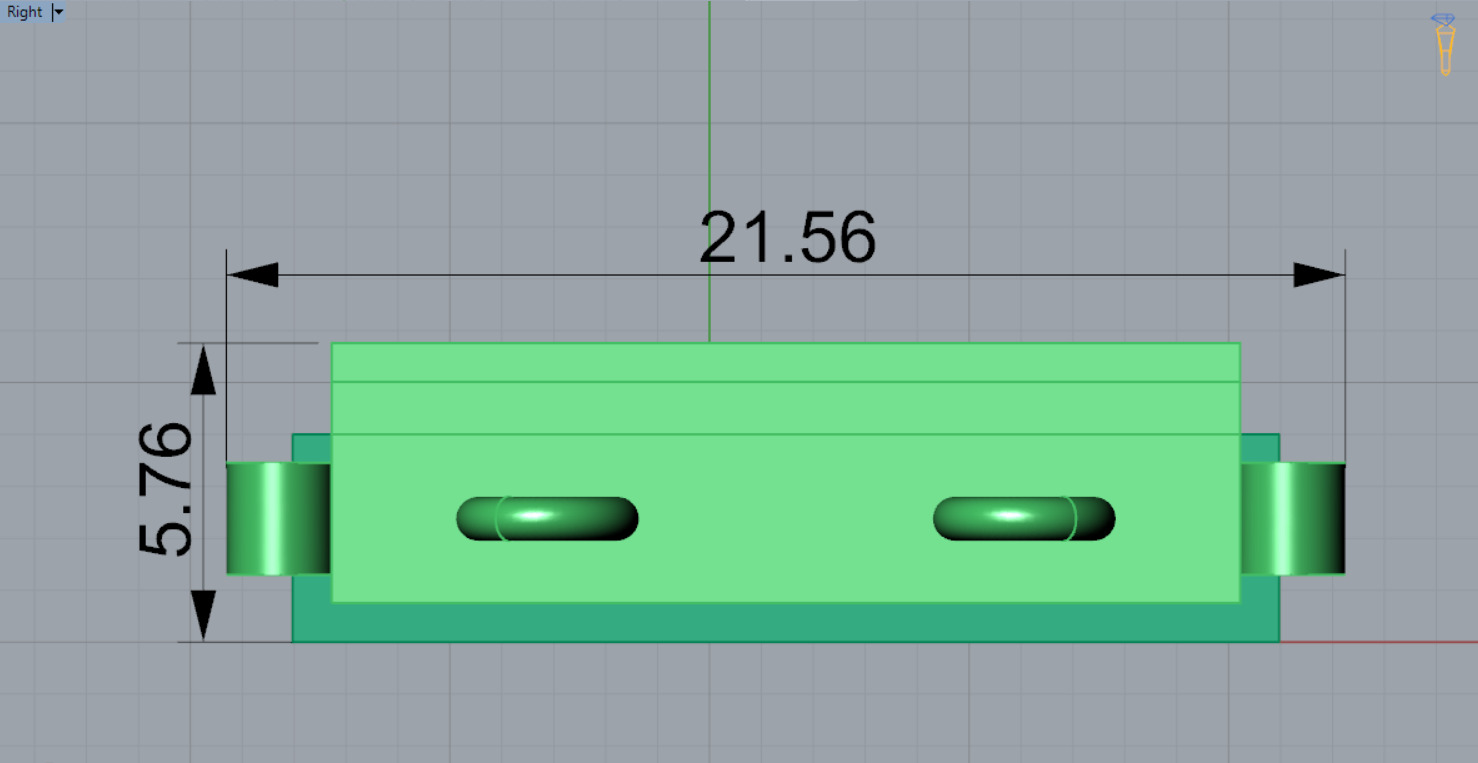
Right View: Displays the side profile, illustrating additional dimensions (5.76) and the arrangement of features. This view also accentuates the component's structure.
The dimensions suggest it's a precision-engineered part, likely intended for mechanical assembly or functional applications within a larger system. The overall clear and neat presentation indicates it may be part of a design proposal or technical documentation.
#3Ddesign #CAD #mechanicalparts #engineering #productdesign #prototyping #3Dmodeling #manufacturing #digitalfabrication #designengineering #techinnovation #mechanicaldesign #technicaldrawing #solidworks #fusion360 #autodesk #modelmaking #precisionengineering #3Dprinting #creativity #designinspiration #productdevelopment #mechtech #industrialdesign #innovation #conceptdesign #parts #engineeringdesign #cnc #designprocess #visualization #prototype #customparts #mechanism #fabrication #makerspace #3Dtechnology #designthinking #objectdesign #mechanicalassembly #engineeringart #partsdesign #hiresmodel #digitaldesign #simulation #prototypedesign #partsassembly #tolerance #construct #engineeringlife

3D Model formats
Format limitations
- Rhinoceros 3D (.3dm) (4 files)5.01 MB
- OBJ (.obj, .mtl)883 KB
- Stereolithography (.stl) (2 files)989 KB
- Autodesk FBX (.fbx)117 KB
- DXF (.dxf)508 KB
- 3D Studio (.3ds)183 KB
3D Model details
- Ready for 3D Printing
- Publish date2025-03-16
- Model ID#5965348
Similar Models

Users who bought this item also bought...
