1/23
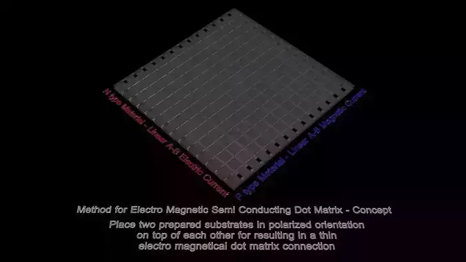
Method for Electro Magnetic Semi Conducting Ultra Fine Dot Matrix - Concept.
Vectorized Linear 1-step Design, down Scaled Electro Magnetic Ultra Fine Semi Conductor Matrix - Stepper Motor Resolution Limit. in the following images, the red thin lines are a electric anode, and the blue lines are a magnetic secondary cathode. the electricity is sent along one axis, resulting in a connection point, where magnetism is created in a perpendicular manner, occupying the other axis. X axis - Electricity, and Y axis Magnetism readout possibilities.
a subtractive method for creating a ultra fine, semi conductor matrix, at home, using household appliances, often readily available. like a 3d laser engraver, a 3d inkjet printer which we can modify, to print ferrofluids, and then harden out and or vaporize excess material with a microwave or even Air-fryer oven. as long as the edged lines are extremely thin, and can be filled with conductive materials. and the microwave is no longer needed for heating actual food. if we can vaporize or heat erode [deliberate oxidation] away excess conducting material, while still being able to make contact we can scale down the modular system and or process even further. since the shape of the design is mathematically spaced and geometrical, we can sand or file away material, and leave as thin a layer as we physically can still make and test contact of, by filing it away from the top of the triangle shape.
1 laser engrave or edge tightest possible linear slits into a glass substrate. edging in a line, leaving open the next, as close as possible to a lasers stepper motor to be able to still do it and keep them separated, non conductive state. in this concept the laser printers ppi and laser engraving ppi are the limiting factors for home creators, as we can vectorize and scale down designs mathematically. as long as the absolute geometry, still does what we need it to do.
2 fill the slits with N-type- P-type materials - hardened ferro fluid or organic epoxy conductor using a laser printer high ppi density. or just filling the slits with conductive fluid that we can harden and remove from later.
3 sand blast or grind away the bottom layer and top of the pyramid to expose tiniest, atomically thin, possible linear slit parallel rail contacts. the thinner the lithographic diode, the least amount of energy is needed to travel through it.
4 turn one plate with P-type fill 90 degrees and rotate entire plate to polarize slits 90 degrees with N-type slits to make a cross hatching super fine dot matrix connection of locations or points that we can still measure electro magnetically as in their absolute electricity and magnetic strength, path length and thus timing and even pre known polarization. the thinner both slits of the same dimensions are, the smaller the absolute contact point, or vectorized atomic dot.
5 perhaps a microwave can vaporize excess materials afterwards heat shrinking the designs absolute geometry even further.The cross sections location where both conductors meet creates a absolute length and thus strength and Time to the detector as well as a magnetic polarization N-S because of this.
the stepper motors single step is the absolute limit as we can vectorize and scale or minimize designs mathematically to below the eye, screen, and lasers light resolution - we dont need to see in order to measure and know electricity, nor magnetism. we need one thin edge, to be a mathematical straight line thick, and one empty line ad infinitum.
if we manage to have the matrix dot give off a preferred color of light on a specific location in/on the matrix by managing the electric current, we have a LCD type structure. we could create a local light value in stead of a color as a digital mask as well. if we measure the magnetic polarity of the perpendicular induced magnetic fields, we have a new type of semi conductor. the electricity must pick a side where it wants to leave by, and it will take the shortest absolute path, straight out of the matrix, this results in a magnetic field line strength output number that we can measure and then use.
the shortest path taken, creates an absolute length the signal will travel, as electricity, and as magnetism. the combined information, results in a pinpoint accurate location through calculation, to determine where the crossing must have happened, must happen, or will happen. if the electric magnetic sideline, moves to the left side, a certain measurable, checkable magnetic polarization of that individual field line will occur.
REVIEWS & COMMENTS
accuracy, and usability.


