1/33
Suspended Inverter Magnet Motor - Concept.
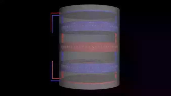
the setup consists of 3 inverter magnets, magnetic systems held in a holder. one inverter magnet consists of 9 magnets, 8 weaker poles up, and one strong pole down. [depending on their overall orientation]. when two inverter magnets are placed together, the strong core of one, attracts the weak core of the other, yet the strong core attracts the others weaker outer ring magnets, and vice versa. they hold each other close, yet can not push away either, they are in a maglock, a magnetic lock, kept locked on a certain distance from each other.
there are two pancake coils, inducing a single! magnetic flux direction together!, as one is charged positive, and one is charged negatively. there are two coils, one on top, and one on the bottom. on pushing, the other pulling, forming a magnetic circuit between top and bottom of the motor. a rotating magnetic flux vortex is created between the top and the bottom of the motor apparatus. one coil sends, the other receives. and finally a single cylinder that holds all the parts together.
what makes this system a actual suspended axial flux motor, is the following:
we begin at the bottom, where we put a Positive charge on the bottom coil, this will create a electro magnetic repulsion, repelling the strong core magnet layer right on top of it, influencing the lowest inverter magnet ring, pushing it up and away from it.
the second, middle inverter magnet, repels the inverter magnet below it, with all its poles. all poles that are orientated downward, repel all poles from the lower magnetic ring. both the strong core magnet, and the inverted ring magnets, all repel the ring below, they are each others perfect opposite, their inverted counter part.
then the top ring, is orientated, and configurated, exactly like the bottom inverter magnet, this means, both the lower inverter magnet ring, and the top inverter magnetic ring, are both magnetically aligned, when powered by the coils, they tend to want to lock with each other. the top and bottom ring are attracting electromagnets, only problem is there is a center ring that pushes off and repels both upper and lower rings, away from it.
they upper inverter magnet ring, and bottom inverter magnet ring, attract each other, when electromagnetically powered by the coils, they are forced together by strong electro magnetic induced attraction, and held in place by the cylindrical hull shape, and they both act inwards, onto the central, middle inverter magnet.
hopefully the magnetic rotating flux crushing inward, into the core, acts like a magnetic turning vortex, suspending AND turning the center ring, forcing it to turn and keep turning as long as electricity is supplied to create the outer electro magnets, be forcefully twisted in the counter spinning direction. creating a turning magnetic disc, by creating a pressure from out to in. a friction, forcing the magnets to turn by forcing the outer magnetic rings together.
the system works like a axial gear system, where you need a 3rd gear to get two axis spinning in the same direction. the third inverter magnet ring, completes the circuit. it can be electromagnetically suspended between two poles, to then be turned near frictionless in the center.i actually modelled in two ball bearing rings, per inverter magnet system, to allow for full rotation of all parts independently very easily. between each core and mantle of a single inverter magnet ring, there are [flattened] spheres acting as roller bearings, allowing the mantle magnets to rotate around the core magnet with different polarity. each of the 3 inverter magnet rings has this built in to facilitate easy magnetic flux induced rotation.
Thank you for reading, every like helps me out, have a nice day.
REVIEWS & COMMENTS
accuracy, and usability.


