A stepper motor, also known as step motor or stepping motor, is a brushless DC electric motor that divides a full rotation into a number of equal steps. The motor's position can then be commanded to move and hold at one of these steps without any position sensor for feedback (an open-loop controller), as long as the motor is carefully sized to the application in respect to torque and speed.
Switched reluctance motors are very large stepping motors with a reduced pole count, and generally are closed-loop commutated.
Contents1 Fundamentals of operation2 Types3 Two-phase stepper motors3.1 Unipolar motors3.2 Bipolar motors4 Higher-phase count stepper motors5 Driver circuits5.1 L/R driver circuits5.2 Chopper drive circuits6 Phase current waveforms6.1 Wave drive (one phase on)6.2 Full-step drive (two phases on)6.3 Half-stepping6.4 Microstepping7 Theory7.1 Pull-in torque7.2 Pull-out torque7.3 Detent torque7.4 Ringing and resonance8 Ratings and specifications9 Applications10 Stepper motor system11 See also12 References13 External linksFundamentals of operation
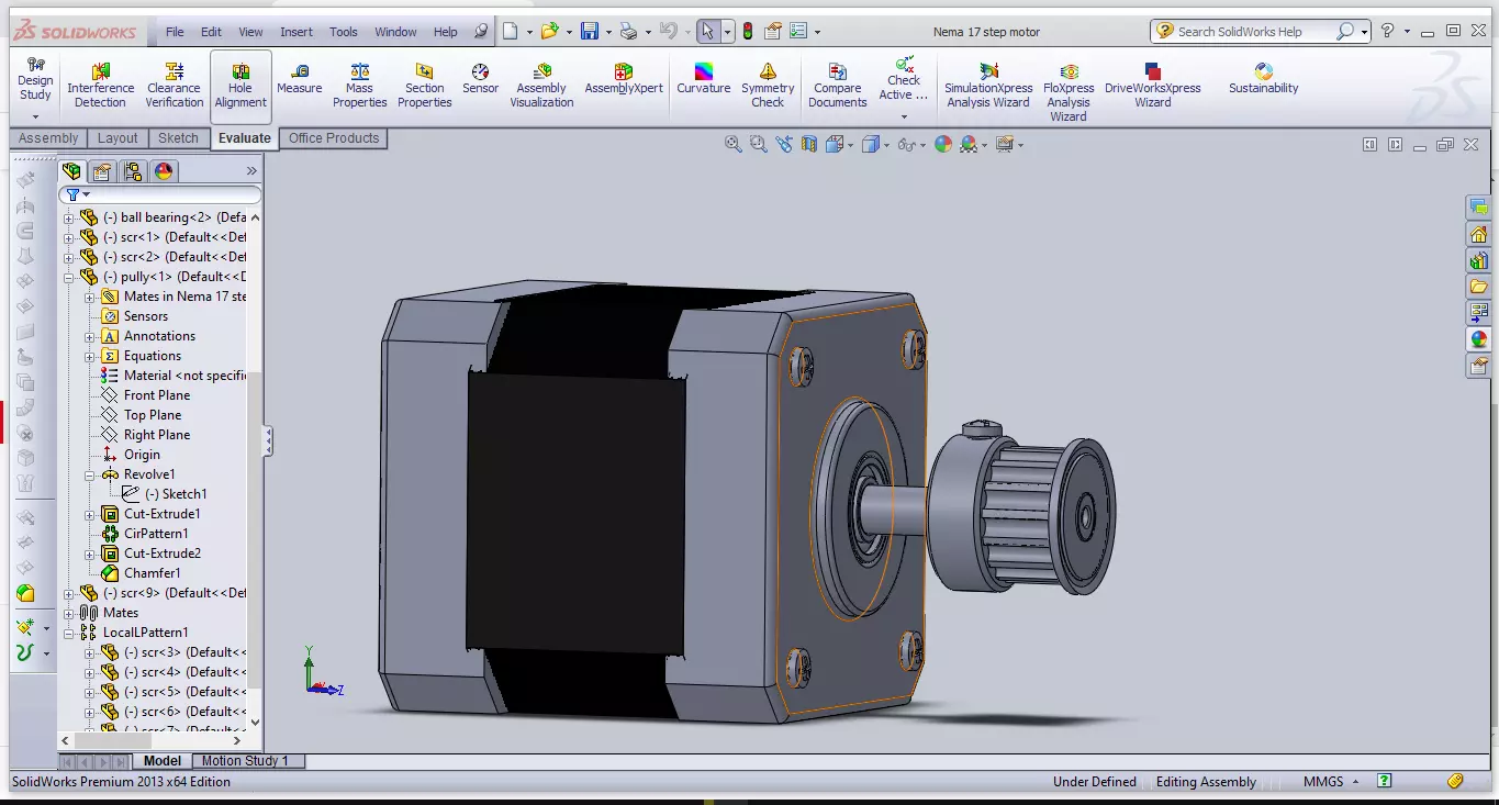
A stepper motor
A bipolar hybrid stepper motorBrushed DC motors rotate continuously when DC voltage is applied to their terminals. The stepper motor is known by its property of converting a train of input pulses (typically square wave pulses) into a precisely defined increment in the shaft position. Each pulse moves the shaft through a fixed angle.
Stepper motors effectively have multiple toothed electromagnets arranged around a central gear-shaped piece of iron. The electromagnets are energized by an external driver circuit or a micro controller. To make the motor shaft turn, first, one electromagnet is given power, which magnetically attracts the gear's teeth. When the gear's teeth are aligned to the first electromagnet, they are slightly offset from the next electromagnet. This means that when the next electromagnet is turned on and the first is turned off, the gear rotates slightly to align with the next one. From there the process is repeated. Each of those rotations is called a step, with an integer number of steps making a full rotation. In that way, the motor can be turned by a precise angle.
The circular arrangement of electromagnets is divided into groups, each group called a phase, and there is an equal number of electromagnets per group. The number of groups is chosen by the designer of the stepper motor. The electromagnets of each group are interleaved with the electromagnets of other groups to form a uniform pattern of arrangement. For example, if the stepper motor has two groups identified as A or B, and ten electromagnets in total, then the grouping pattern would be ABABABABAB.
Electromagnets within the same group are all energized together. Because of this, stepper motors with more phases typically have more wires (or leads) to control the motor.
TypesThere are three main types of stepper motors:[1]
Permanent magnet stepperVariable reluctance stepperHybrid synchronous stepperPermanent magnet motors use a permanent magnet (PM) in the rotor and operate on the attraction or repulsion between the rotor PM and the stator electromagnets.
Pulses move the rotor in discrete steps, CW or CCW. If left powered at a final step a strong detent remains at that shaft location. This detent has a predictable spring rate and specified torque limit; slippage occurs if the limit is exceeded. If current is removed a lesser detent still remains, therefore holding shaft position against spring or other torque influences. Stepping can then be resumed while reliably being synchronized with control electronics.
Clarification- Stepper motor detent is analogous to brushless dc motor cogging. In the case of constant speed brushless dc motor, magnetic cogging is of concern for torque ripple effects