


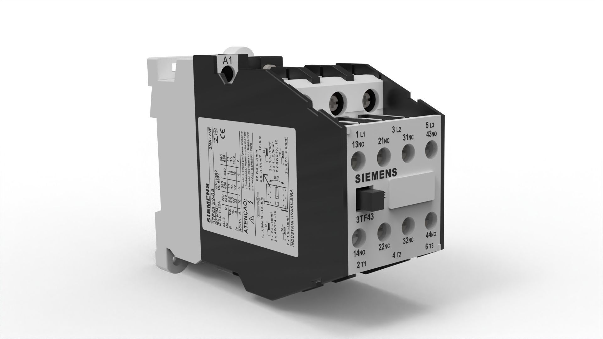
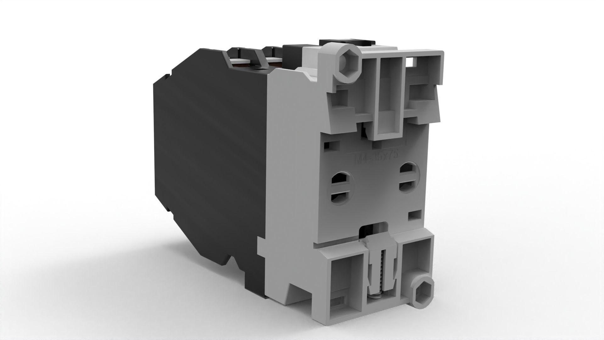
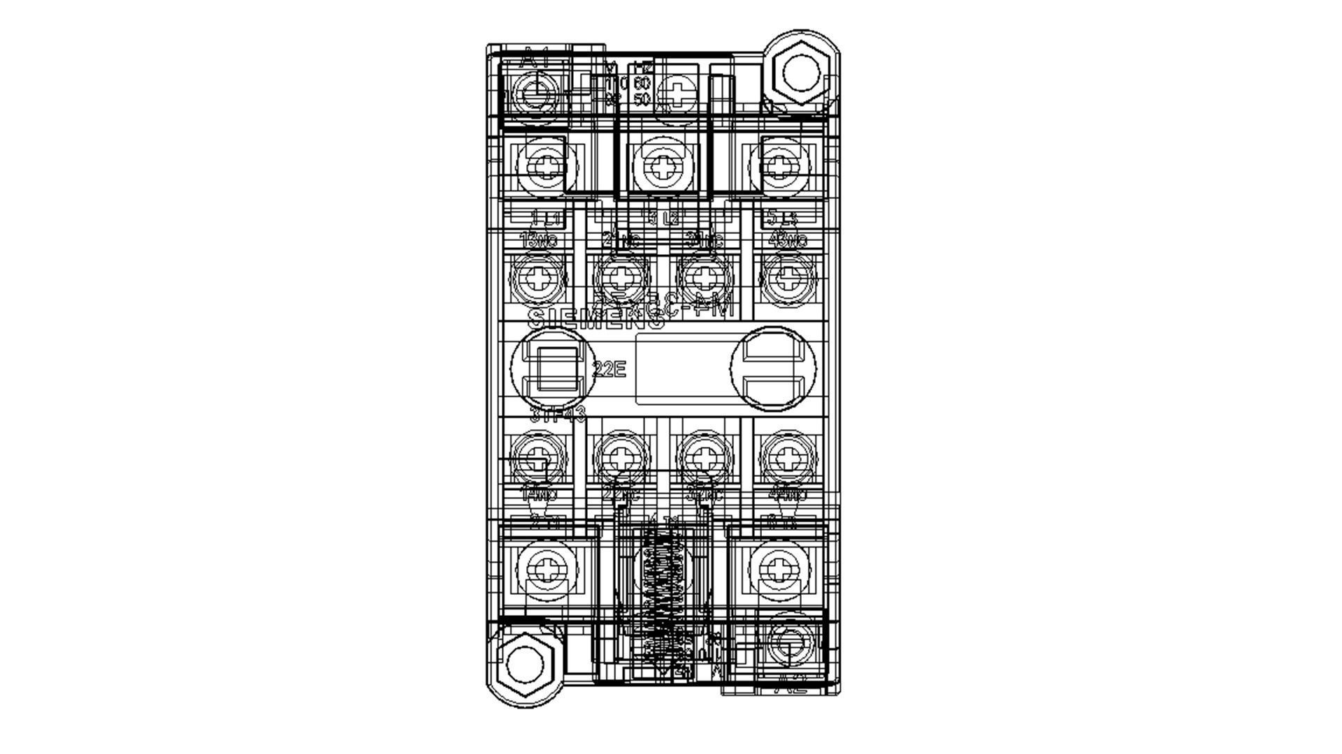
Contactor Low-poly 3D model
This product has been designed with high accuracy and realistic measurements and can be used on all programs and all uses from internal or external design or making a motion video or showing it with more than one work
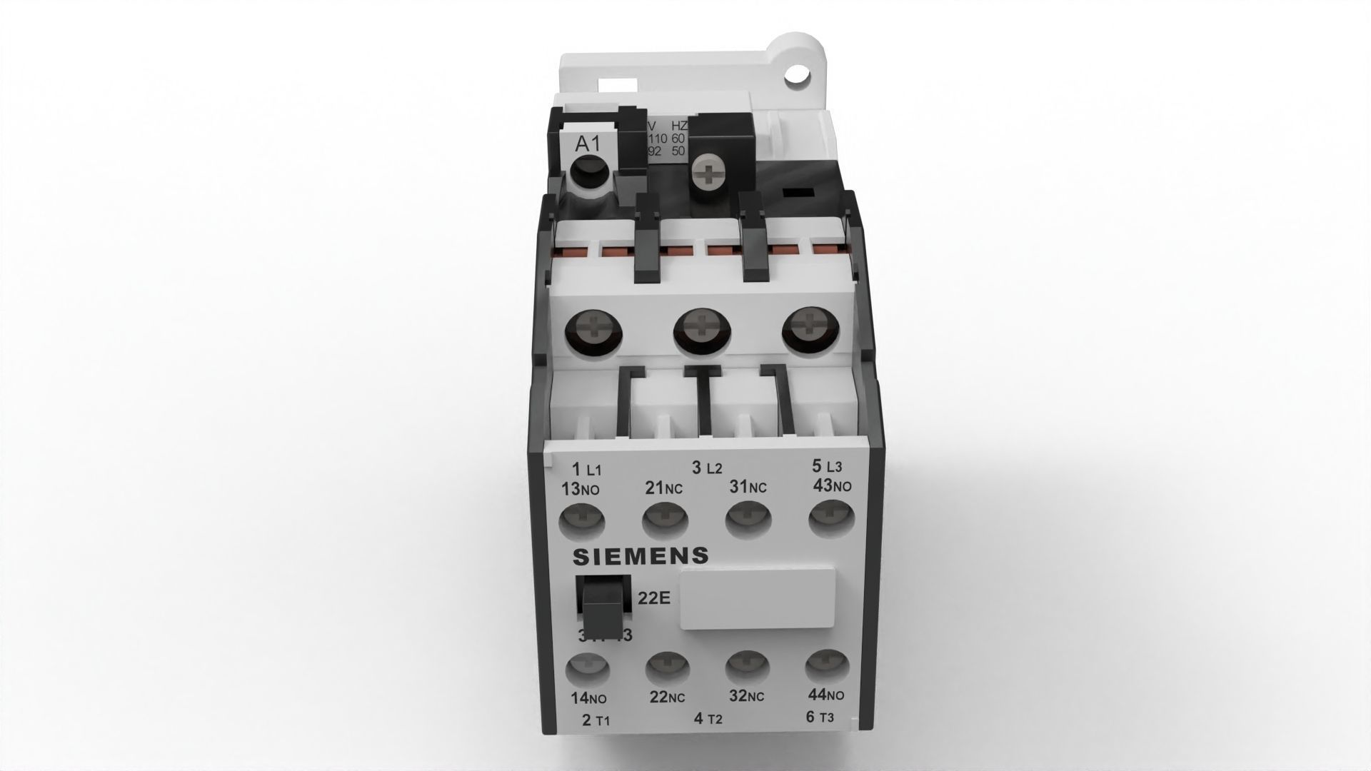
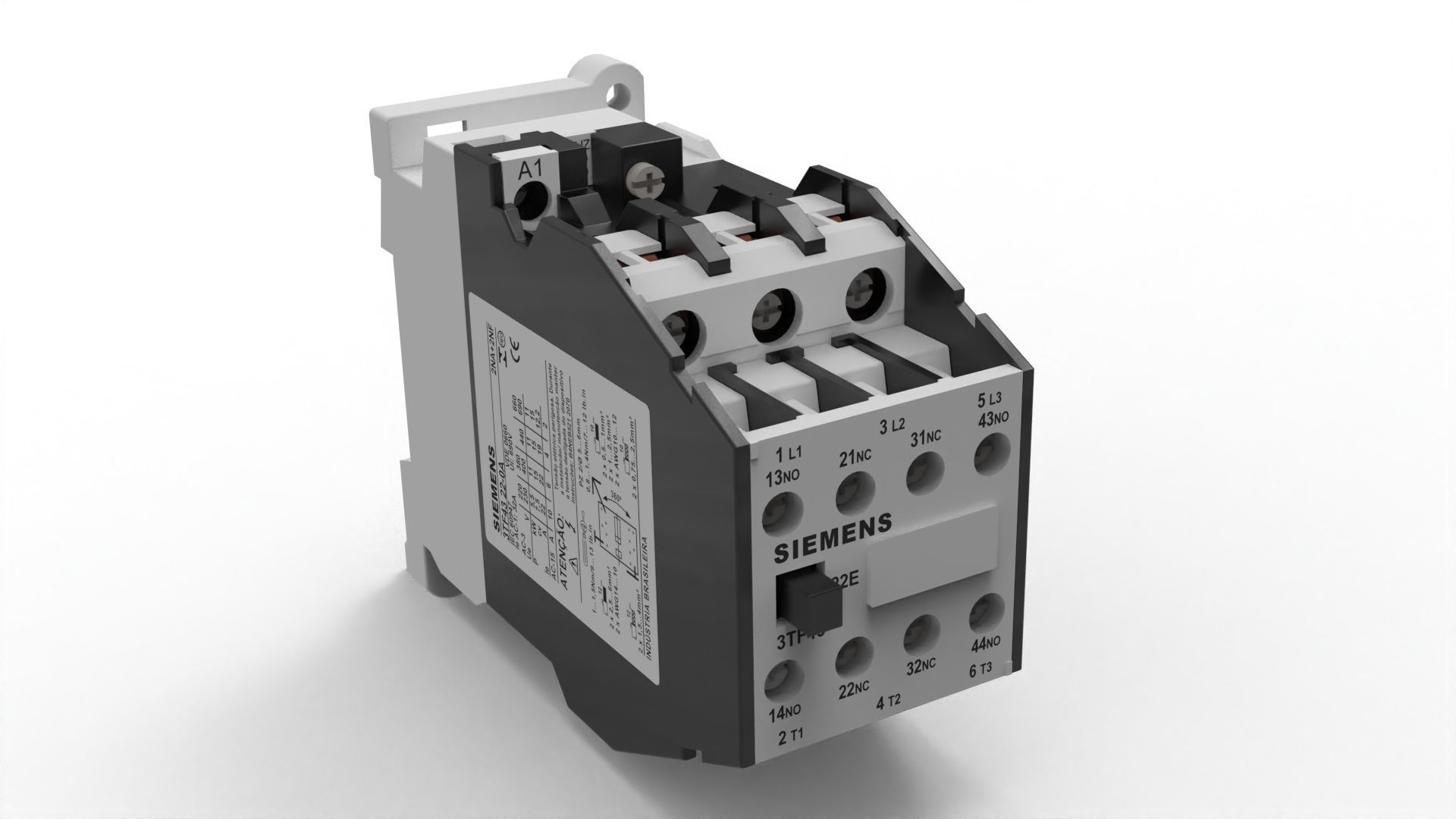
An electrical contactor is an electromechanical device used for controlling the flow of electrical power in a circuit. It is essentially a switch that is operated by an electromagnetic coil. Contactors are widely used in industrial and commercial applications to control motors, lighting systems, heating elements, and other electrical loads.
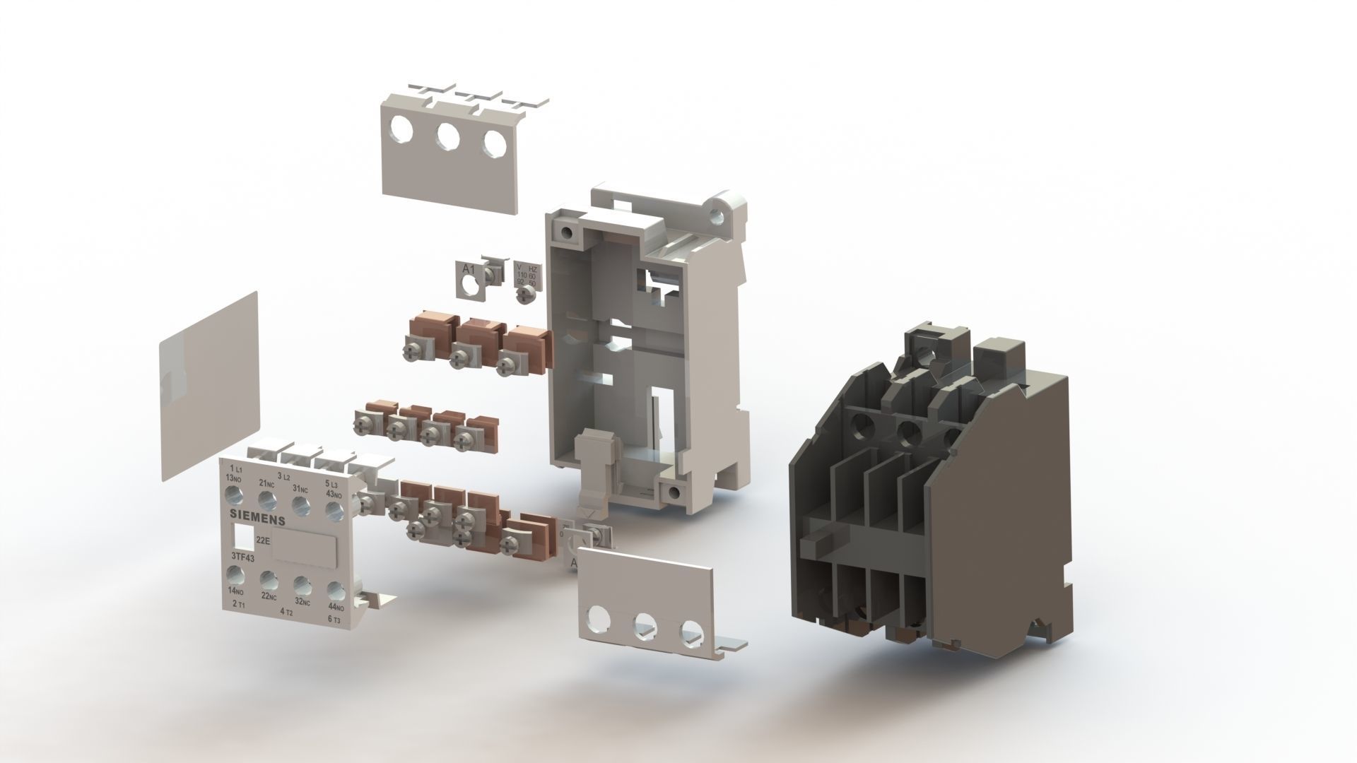
Here are some key components and features of an electrical contactor:
Coil: The coil is an electromagnetic winding that generates a magnetic field when an electric current passes through it. This magnetic field is used to control the opening and closing of the contactor's contacts.
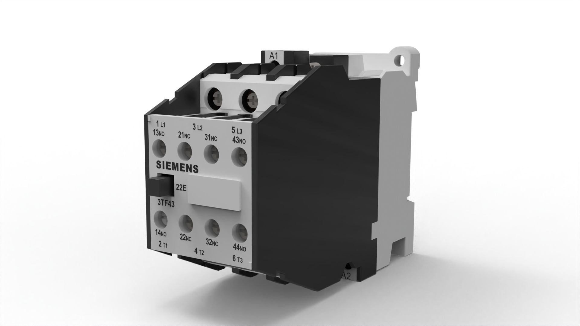
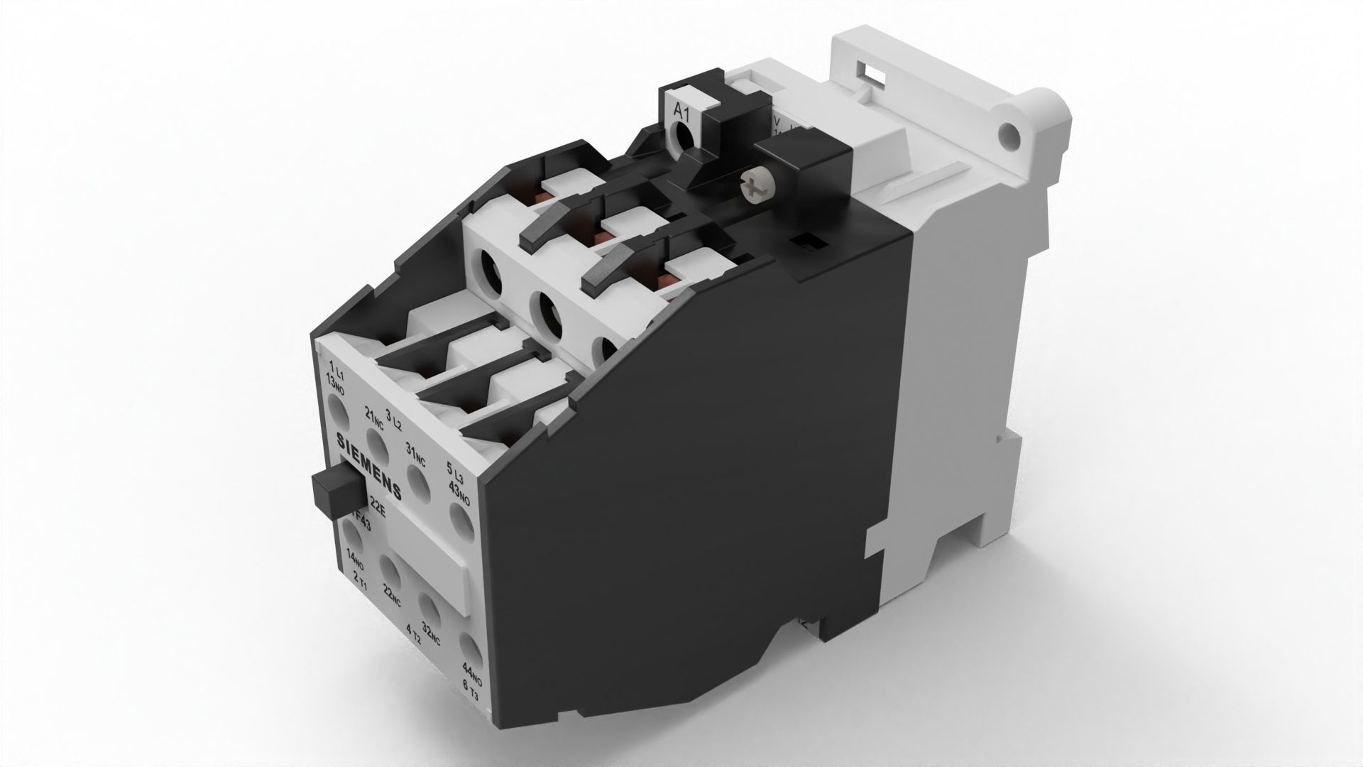
Contacts: Contacts are the main switching elements of a contactor. There are typically at least two sets of contacts: main contacts and auxiliary contacts. The main contacts carry the current to the load, while the auxiliary contacts are used for control signals or auxiliary functions.
Normally Open (NO) and Normally Closed (NC) Contacts: The main contacts of a contactor can be either normally open or normally closed. In the de-energized state, the normally open contacts are open, and the normally closed contacts are closed. When the coil is energized, the contacts change their state accordingly.
Arc Suppression: When the contacts of a contactor open or close, an electric arc may form between them due to the high currents involved. To suppress this arc and prevent damage to the contacts, contactors often incorporate arc suppression techniques, such as arc chutes or magnetic blowouts.
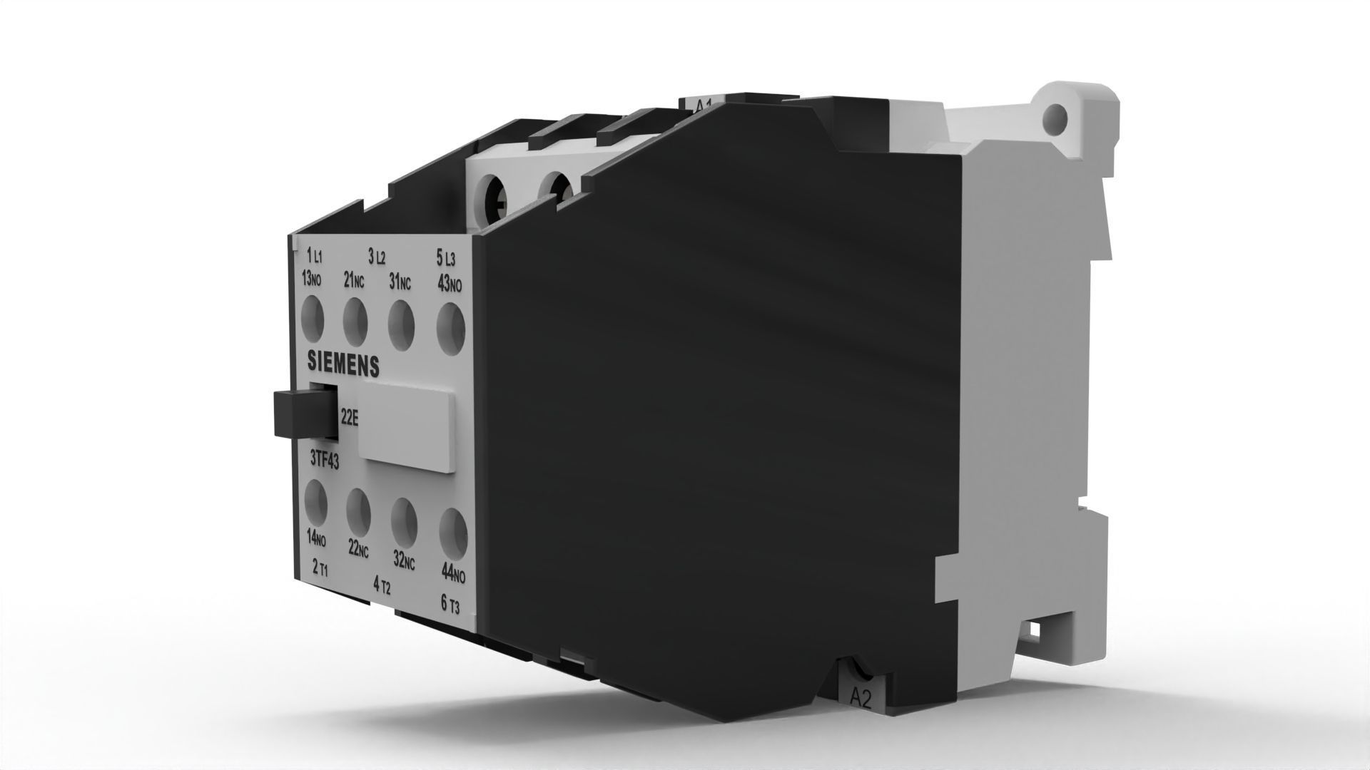
Control Circuit: Contactors are controlled by a separate control circuit. This circuit typically includes a control voltage source, such as a push button, switch, or relay, which activates the contactor coil to close or open the contacts.
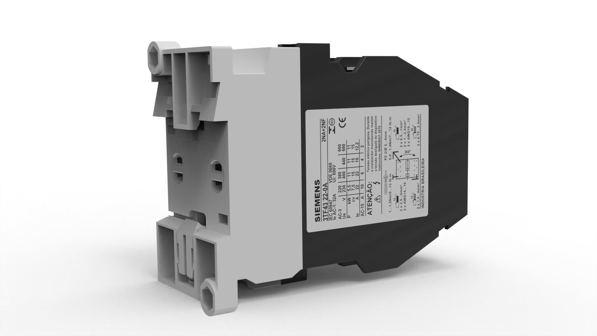
Ratings: Contactors are designed to handle specific voltage and current ratings, and they are selected based on the electrical load they will control. Important ratings include the maximum voltage, current carrying capacity, and the number of poles (typically 3 poles for three-phase applications).
Mechanical Interlock: In some contactors, a mechanical interlock is provided to prevent simultaneous closure of the main contacts and ensure proper sequencing. This interlock mechanism helps prevent short circuits and improves safety.
Contactors are chosen based on factors such as the type of load, switching frequency, environmental conditions, and electrical requirements of the application. They offer reliable and durable switching capability, making them essential components in electrical control systems for various industries.

3D Model formats
Format limitations
- Autodesk 3ds Max 2023 (.max)12.7 MBVersion: 2023Renderer: Arion 2023
- 3D Manufacturing File (.3mf)1.67 MB
- Cinema 4D 2022 (.c4d)6.41 MBVersion: 2022Renderer: Default 2022
- Autodesk FBX (.fbx)1.73 MB
- glTF (.gltf, .glb)5.97 MB
- Autodesk Inventor 2023 (.iam, .ipt)14.1 MBVersion: 2023Renderer: Octane 2023
- OBJ (.obj, .mtl) (2 files)10.2 MB
- SolidWorks 2022 (.sldprt, .sldasm, .slddrw)16.3 MBVersion: 2022Renderer: Mental Ray 2022
- Blender 3.2.2 (.blend)13.8 MBVersion: 3.2.2Renderer: Default 3.2.2
3D Model details
- Ready for 3D Printing
- Animated
- Rigged
- VR / AR / Low-poly
- PBR
- Geometry Other
- Polygons 141,938
- Vertices 131,849
- Textures
- Materials
- UV Mapping
- Unwrapped UVs Unknown
- Plugins used
- Publish date2023-05-15
- Model ID#4502977
Similar VR / AR / Low poly 3D Models

Users who bought this item also bought...
