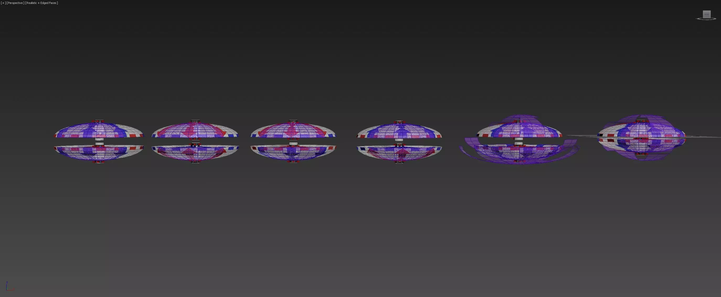
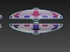
Bi-Directional Ionwind Compass - Concept
6 modes, all serving a different purpose.
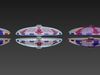
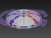
one could 3D print the hemispherical shapes and plate them with tinfoil, inner and outer surface area can be plated and used as the 3D print of the structure in the middle acts as an insulator, separating the inner and outer hull sections.
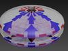
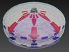
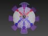
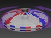
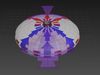
in mode 1 only a quarter of the top and bottom half are charged, in the center there is a ring with a circuit needle, able to moveup and down, thus either making contact completing the circuit, or not. and is also able to rotate, like a compass, giving direction to the charge.by charging the top half positively, on the top location, and charging the lower location negatively, we force the ion wind down along the hulls inner or outer surface, or even charging them both, as the entire hull is made out of conducting material, we can use both sides or surfaces to complete the ionwind circuit.
in mode 1 the lower hemisphere circuit is charged 180 degrees in the opposite direction, giving the lower hemi a different function than the we gave the top half. here we charge the center smaller ring positively, and force it outward towards the outer hull, and then downward.
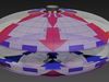
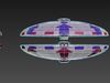
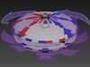
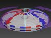
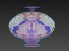
mode 2 is the complete opposite of mode 1, as both hemispheres now push ionwind down and up.
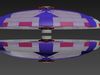
mode 3 we find the first useful configuration for achieving lift, as both hemispheres work together performing the same task while having a opposite direction of flow, inverted as it were.
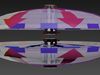
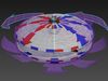
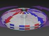
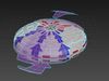
mode 4 might be useful to move downward, very quickly, make sure the device has altitude before engaging this mode.
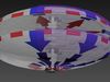
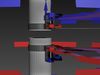
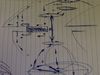
in mode 5 we divided both hemispheres even further, creating a direction of flow, over the entire hull. now we charge the tip, or nose direction, and do the complete opposite, behind the device. here the front and back half hemispheres work together, to move into a direction. in mode 5 i have left the bottom hemi forcing the ionwind downward, and the top half directional, creating a little motion towards this location of charge.
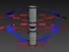
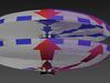
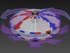
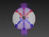
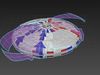
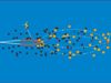
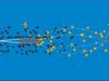
in mode 6 we have the faster motion, as all 4 quarter hemis now work together for moving into a preferred direction. the top nose is charged negatively, and the higher top is charged positively. the bottom nose/front is charged negatively, and the bottom center ring negatively.by turning the center ring needles, or contacts, we can create a direction of motion as all forces will work together towards a certain preferred direction. the tip of the craft will be charged positively, and the back of the craft negatively, two separate circuits, working together in different configurations towards any preferred direction.
glad i have this out of my system now... this stuff gets harder and harder to explain...
i live off of comments, your likes and your tips. thank you for watching and reading.